Electric Hot Water Generators: Efficient Water Heating with Electricity
Electric hot water generators are specialized devices designed for water heating using electricity as the primary energy source. These generators are equipped with multiple tubular heating elements, typically constructed of copper plated with nickel‐chromium. When electricity is supplied to these elements, they heat up and transfer that thermal energy to the surrounding water. They play a crucial role in providing hot water for heating systems, industrial processes, and domestic use.
Core Components of Electric Hot Water Generators
The core components responsible for controlling the operation of the hot water generator include:
a. Control Module
b. PID Controller
c. Step Controller
Control Module:
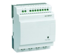
The Control Module serves as the central control unit, overseeing all safety measures, interlocks, and connections to the Building Management System (BMS) for remote operation. It ensures the safe and efficient operation of the system.
PID Controller:
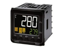
The PID (Proportional‐Integral‐Derivative) controller regulates the water temperature within the unit. Users can set their desired temperature as the Set Value (SV), and it displays the current running temperature as the Process Value (PV). The PID controller continuously calculates the difference between SV and PV, employing a proportional‐integral‐derivative algorithm to provide an analog output to the Step Controller.
Step Controller:
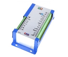
The Step Controller is a microprocessor‐based multi‐stage electronic progressive sequencer that manages the unit in stages. The total number of active stages is determined by the analog input signal received from the PID controller. In case of an open or shorted input, all stages are switched off for safety. The Step Controller orchestrates a linear sequence of contactor stages for multi‐branch loads, with Stage 1 being the first to activate and the last to deactivate. Selectable time delays dictate when stages are added or removed. Additionally, the Step Controller features a built‐in test mode that cycles through the selected number of stages with a 1‐second delay. This mode facilitates the verification of load wiring, contactor operation, and stage functionality.
As the demand for hot water increases, the temperature delta between the SV and PV values widens. This signals the Step Controller to activate the heating stages, ensuring the appropriate amount of heating capacity is employed.
All safety mechanisms are intricately connected to the heart of the unit, which is the Control Module. The Control Module continuously monitors the health of these safety features and only authorizes the Step Controller to activate the heating stages when all safety checks are satisfied, maintaining the safety and reliability of the system
Control Module
PID Controller
Step Controller
